
Creating Artwork with Gradient Mesh in Illustrator
Experience the joy of meshing things up.
This article appears in Issue 41 of CreativePro Magazine.
Let’s get one thing straight from the start: Gradient Mesh is awesome. I have loved it ever since I discovered it via Brooke Nuñez’s tutorial for creating a red pepper. In this article—my ode to the very talented artist that showed me the art of gradient mesh—I will show you how to grow your own mesh pepper from a photo.
If you want to follow along, click here to download the example file. While you may never need to create artwork of a pepper, the techniques in this tutorial can be applied to any other subject.
Plant Your Seed on the Artboard
First, you need to prepare the reference photo in Illustrator. Create an artboard of any size, choose File > Place, and navigate to the example peppers image. Click Place to attach it to your pointer, and click your artboard once to place the image at 100% scale. Double-click the image with the Artboard tool to resize the artboard to match it. To fit the artboard to your screen, press Command+0 (macOS) or Ctrl+0 (Windows) (Figure 1).

Figure 1
In the Layers panel, double-click the area to the right of the words Layer 1 to open the Layers Option dialog box. Turn on the Template option, turn off Dim Images To (Figure 2), and click OK.
Figure 2
Add the First Mesh
Successfully applying Gradient
Mesh is all about visualizing the subject as a collection of components, so take a look at the two peppers in the image. You can separate each pepper into eight parts (Figure 3). We’ll concentrate on the red pepper in this tutorial, so use the Eyedropper tool to sample its red as a fill color.
Figure 3
Now let’s add a simple mesh. Create a rectangle over the front of the pepper, covering Part 1. Choose Object > Create Gradient Mesh, and in the dialog box that opens, create a mesh of 2 rows by 2 columns (Figure 4) and click OK.
Figure 4
Now the red square covers half the pepper, so you can’t see it. Bummer, eh? Not really. Illustrator allows you to view your progress in real time while working with meshes. To do so, choose Window > Navigator to open the Navigator panel, which shows a preview of your project. I like to resize this panel to half my screen and work in the other half (Figure 5).
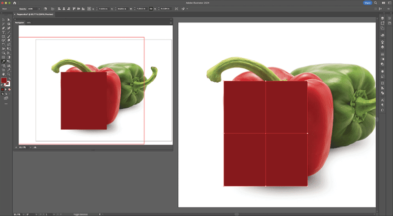
Figure 5
Choose View > Outline, and—whoa, x-ray vision—you can see the artboard in a transparent view, while watching your progress come to life in the Navigator panel (Figure 6).
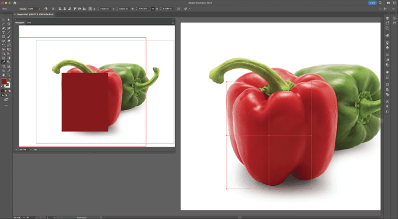
Figure 6
Manipulate the Anchor Points
Here is where the mayhem starts. While working in Outline mode on the artboard and watching the progress in the Navigator panel, we’re going to manipulate the mesh’s anchor points to adjust its shape to better simulate the curvature of the pepper. You’ll select and move anchor points individually, adjusting their handles to curve the bounding box to conform to the shape of the front of the pepper.
A bit of setup will make this scaling process easier: First, turn off (uncheck) snapping by choosing View > Snap to Point and View > Snap to Glyph, and resize the rectangle so the sides are touching the shape. So that you can easily toggle between them later, select the Direct Selection tool and immediately after select the Anchor Point tool, which is in the Pen tool’s menu. Practice switching tools by pressing the Command (macOS) or Ctrl key (Windows).
Ready? While the Anchor Point tool is active, press and hold the Command/Ctrl key to switch to the Direct Selection tool. While still holding, drag the top-center anchor point into the small nook at the top-front part of the pepper (notice the anchor point handles disappear). Next, drag the center anchor point down and slightly to the left, to simulate the shape’s curvature (Figure 7).

Figure 7
Release the Command/Ctrl key and notice how the handles reappear to the left and right of the anchor points. Working one by one, press Command/Ctrl and use the Direct Selection tool to select an anchor point, toggle to the Anchor Point tool, and adjust the point’s handles individually to convert the straight lines into curves that follow the contour of the shape (Figure 8).

Figure 8
At the end, you will have the front of the pepper (Part 1) within the first mesh shape (Figure 9).

Figure 9
Note: Do not select the anchor points with the Anchor Point tool as the handles will disappear.
Create the Mesh Grid
With the anchor points in place, you’re ready to create the mesh lines. For this tutorial, we’ll keep the number of lines low for easier viewing. Ordinarily, I would create twice as many. To start, choose View > Preview so you can see the actual shape on the artboard (Figure 10).
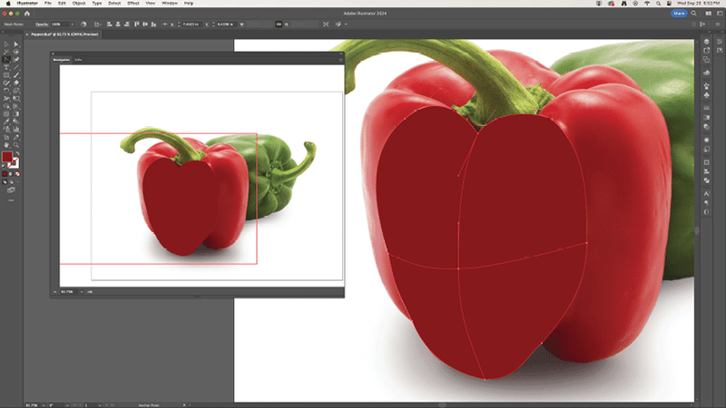
Figure 10
Pretty cool, huh? Now it’s time to convert the shape into a mesh grid.
Study Figure 11A for highlights, shadows, bumps—basically, any sort of imperfection you find within the shape. These imperfections dictate where the initial mesh points and lines should be placed in the grid. Using the areas indicated in Figure 11B as a guide, add mesh points precisely on top of the highlights and shadows.
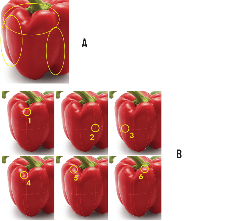
Figure 11
Next, add the mesh lines to create the first mesh grid (Figure 12). Do your best to space them out evenly for this exercise.
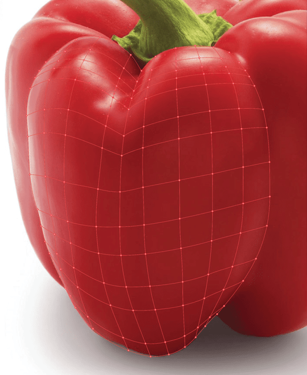
Figure 12
Add the Gradient
Time to make the magic work. Click the Direct Selection tool, then the Eyedropper tool so you can easily toggle between them. Command/Ctrl-click one of the anchor points with the Direct Selection tool, and then toggle to the Eyedropper tool (press Command/Ctrl) to sample the color closest to the point. In the Navigator panel, notice that section of the red pepper changed color. Excellent. Now follow the same procedure for the entire grid. You can see the progress of the mesh coming together in Figure 13. Continue this procedure until the entire grid has been converted into a nice, smooth gradient (Figure 14).
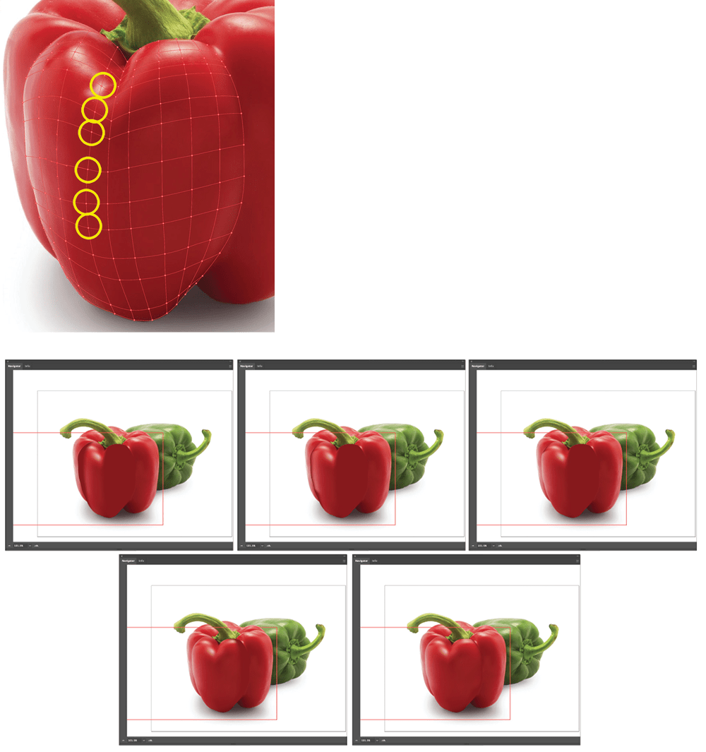
Figure 13

Figure 14
That’s how it gets done! You will follow this same procedure for the remaining parts of the pepper.
While working on subsequent portions of the pepper, you need to keep in mind the order of the layers. Some portions should be put behind certain areas in order to simulate blending and create the illusion of a seamless mesh. For Part 2 of the pepper, create a new layer under the Red Pepper Front layer. Do your best to align the new mesh lines with the previous mesh (Figure 15).
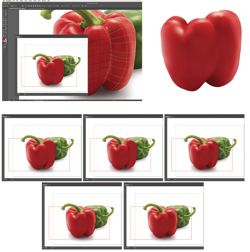
Figure 15
This will help in creating a seamless mesh. It’s all trial and error, so give it your best shot.
Figure 16 illustrates Part 3. Again, keep in mind the order of the layers.
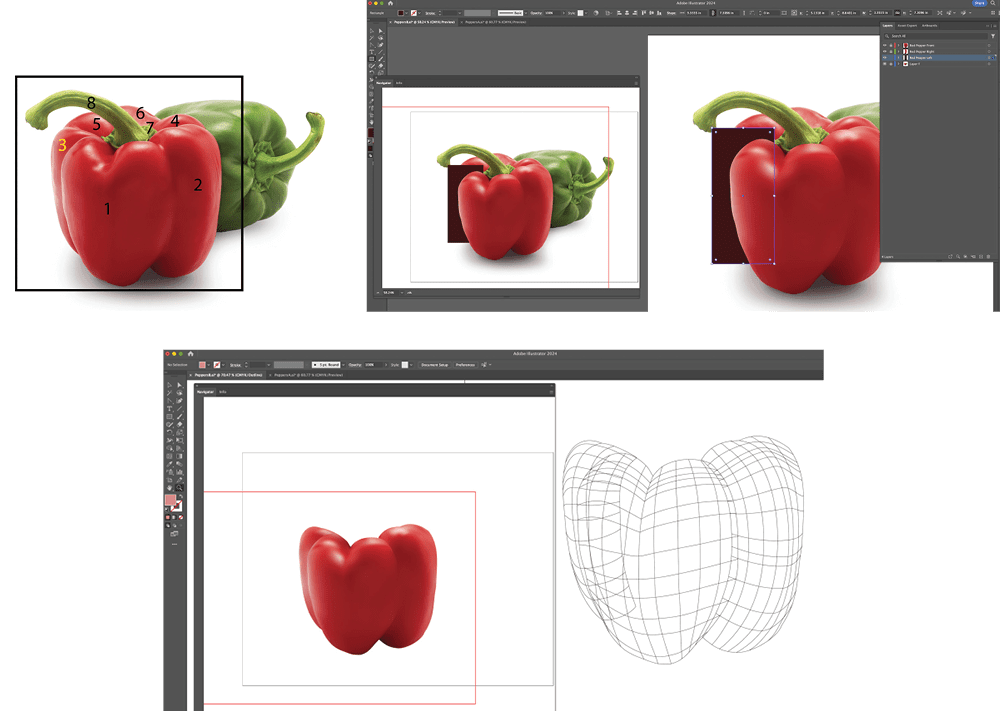
Figure 16
The stem of the pepper is a little bit tricky. Create a 2 × 2 mesh grid, sample the color, position it in the closest angle to the direction of the stem, and then go into Outline mode (Figure 17).
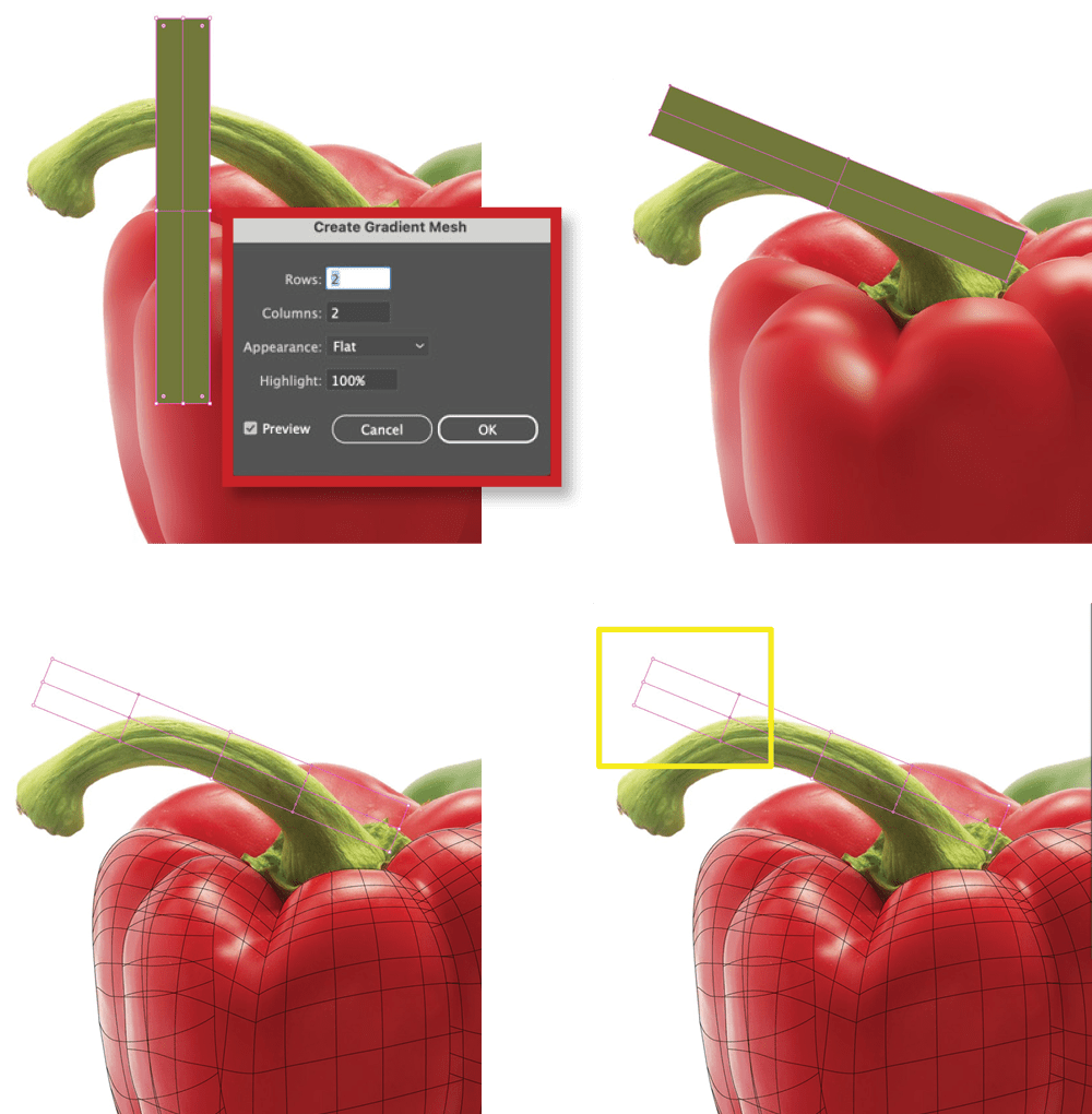
Figure 17
Let’s improve the stem angle: Select the top six anchor points with the Direct Select tool, and then click Rotate. Drag to rotate those six anchor points to mimic the curvature of the stem and place it closely to match Figure 18.
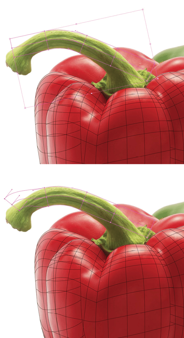
Figure 18
The main thing is to align the center mesh line with the center of the stem (Figure 19). Continue this procedure throughout the entire stem; adjusting the points with the Direct Selection and Anchor Point tools.
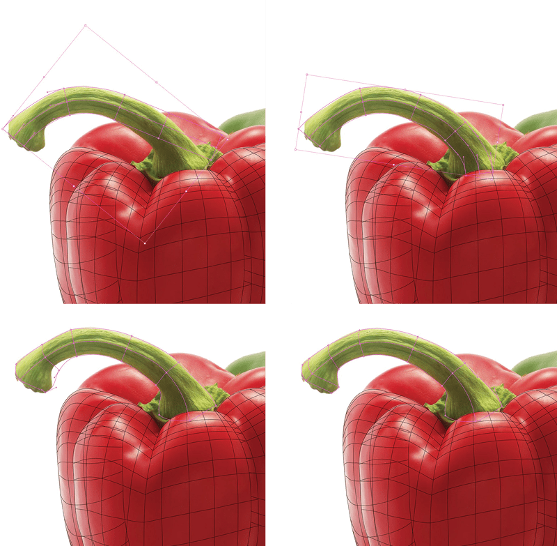
Figure 19
Continue adding mesh lines and adjusting handles. Place the stem’s layer under the Red Pepper Front layer, and sample the colors until you have the completed stem (Figure 20).

Figure 20
Parts 5 and 6 can be completed with one mesh (Figure 21).
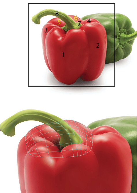
Figure 21
Finish up with Part 4; the final part of the pepper (Figure 22).
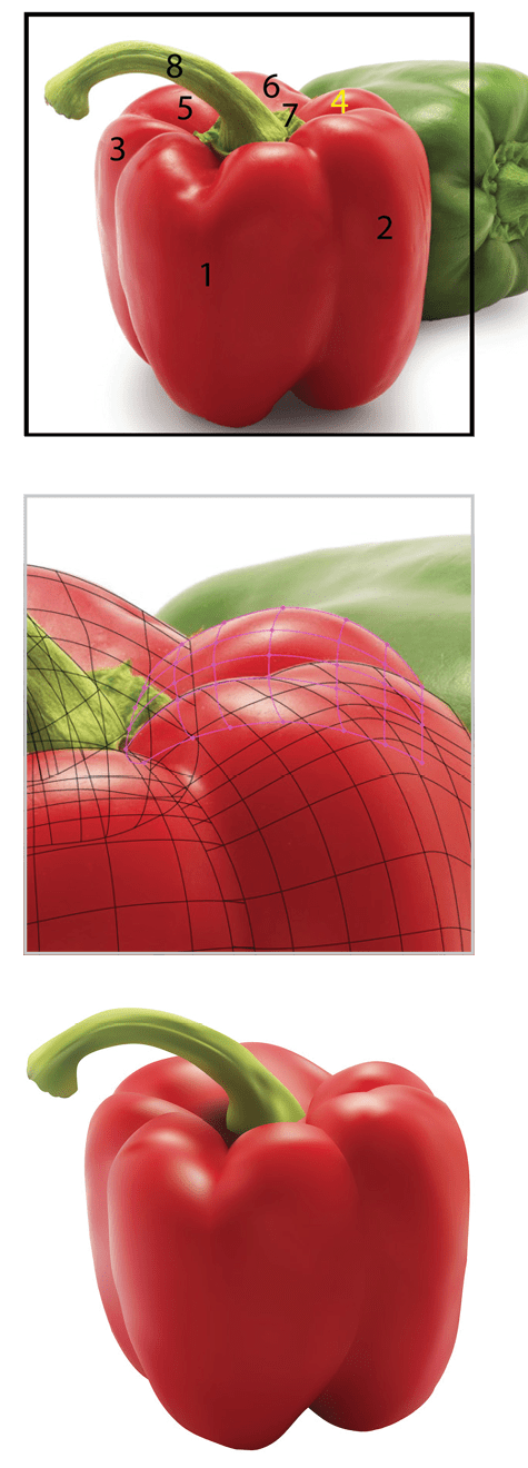
Figure 22
Part 7 will be the most challenging of this project because it is not a shape that can easily be traced (Figure 23).

Figure 23
Normally, I would not add a very complex mesh to areas like this, but it is a nice enough challenge to see just how well a 2 × 2 grid can be manipulated and adjusted. Areas like this are all trial and error. Take a look at the series of images in Figure 23 to see how this was accomplished and experiment with the same method until you get the desired result (Figure 24).
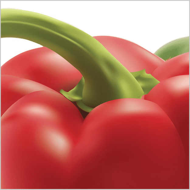
Figure 24
Now we have a completed red pepper created with basic meshes (Figure 25)!
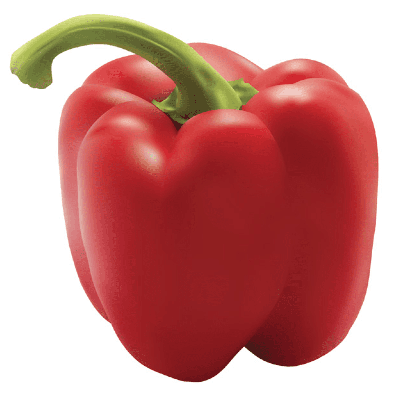
Figure 25
There’s Always More to Mesh
Congratulations on making it to the end of this tutorial! Creating artwork with these techniques isn’t simple or quick, but the detailed results you can get can’t be achieved by other method (sorry, AI!). And believe it or not, we’ve just scratched the surface. There’s much more you can do with meshes, including creating shadows and textures. But that’s a story for another day. For now, if you’d like more tips on creating Gradient Mesh effects, check out my article on CreativePro.com.
Have fun meshing things up!
Commenting is easier and faster when you're logged in!

Recommended for you

Clear Text Overrides from Word Files
WBB wrote:This is an age-old problem for me... How do I get my Word styles to im...

InReview: iziExport
Plug-in gives you a head start in moving content from InDesign to WordPress.