
This article appears in Issue 8 of InDesign Magazine.
Ahoy, mateys! Scuttlebutt has been that anchored objects in InDesign are naught but overly complicated, deadweight rigging. Well, hoist the mainsail, drop the bowline, and batten down the hatches. Let’s see what her anchors can do.
Before InDesign had an anchored objects feature, illustrations, figures, callouts, charts, tables, pull quotes, sidebars, tip boxes, and all those other things that must accompany text flows but drift outside them were treated like unrelated vessels. That is, when the story reflowed, designers had to manually steer the rest of the boats back into the fleet. Yargh, them were stormy seas!
In proper nautical terms, anchored objects are more accurately called tethered objects. They aren’t, after all, anchored to a particular location on the page, but rather they’re tethered to the lead ship: the story’s text. Where it sails, so shall the objects tethered to it.
Take this market analysis report (Figure 1), which is typical of any illustration- and figure-laden, multi-page document. Here we have sidebar illustrations (left), as well as a sidebar text frame (top right) and an illustration the width of the page (bottom right). There are also inline illustrations in the form of section headings, which are text frames separate from the main threaded story frames.

Figure 1. Anchored objects abound, making everything instantly adaptable to text reflow.
We’ve all made documents similar to this, and we’ve all had the tedious chore of moving the documents’ figures, sidebars, and so forth to adapt to last-minute reflows in the copy they support. Anchored objects nullify the need for that particular chore.
In the event of a reflow, like that shown in Figure 2, all of the supporting elements can follow the text, automatically, and even flip orientations—jumping from the sidebar of a left-read page to a mirrored placement in the sidebar of the right-read—without your manually touching a thing.

Figure 2. When copy or layout changes earlier in the document add a new page, the text reflows, as do the charts anchored to it.
You have two ways to make anchored objects: You can start with the content or with the container. Let’s learn the basics on smooth seas before heading into the chop.
1. Build the vessels
Set your body copy text frame (or threaded frames) to serve as the lead ship in this fleet of objects. Then create or place your first illustration (or chart, pull quote, or whatever) anywhere on the page. Style it as you like, and, if the to-be-anchored object requires multiple pieces—a caption or a photo credit, for example—group them together with their illustration. I’ve created a grouped chart and caption off on the pasteboard (Figure 3).

Figure 3. My chart and caption are grouped, allowing me to work on them as a single anchored object.
2. Hitch the knot
Select your object or group with the Selection tool, and cut it to the clipboard (Edit > Cut). Now grab the Type tool and, just ahead of the text to which the anchored object must be tethered, paste with a normal Command/Ctrl+V (don’t Paste in Place). You should wind up with some calamitous shipwreck similar to mine (Figure 4). Don’t worry: You haven’t run aground.

Figure 4. Pasting an anchored object into the text creates a temporary, but easily patched, wreck.
3. Secure the anchor chain
With the Selection tool, select the object or group again, and start feeding out the anchor chain by choosing Object > Anchored Objects > Options (Figure 5) and selecting Inline or Above Line.

Figure 5. The Anchored Object Options dialog box, in Inline mode. If you want an inline object (one that appears within, and in relation to the baseline of, the main flow of text) or an above-line object (an object that appears above the line into which it’s been inserted), these are your options.
Choosing Inline allows only a vertical, or y-axis, offset in positive or negative values—for raising or lowering the object relative to the text’s baseline. If your anchored object has a text wrap assigned to it, lines below the insertion point will wrap around it; the line containing the insertion point, however, will not. (See the sidebar, “Give Way to the Stand-On Vessel.”)
Above Line is useful for replacing paragraph rules with something a little more interesting or for putting just about any kind of object ahead of text. It even has Space Before and Space After, which work exactly like their counterparts on the Paragraph panel.
Why doesn’t it have breaks, such as column break before? It doesn’t need them. Remember: The object’s anchor is within the text. If you need a page, column, or other break ahead of the anchored object, apply the break to the text’s paragraph style. Then the break will occur before the anchored object, effectively creating breaks ahead of the object.
The spacing options in this dialog box are merely for padding the distance between the anchored object and whatever comes above and below it.
In the Alignment popup menu are six options: Left, Center, Right, Towards Spine, Away from Spine, and Text Alignment. Although the first three are self-explanatory, the last three might not be immediately clear.
Recognizing that objects are aligned differently on left- and right-read pages in a facing-pages document, InDesign here (and in other places) includes the ability to specify alignment as being relative to the location of the spine. Just as page margins flip from one side of a spread to the other, so too can anchored objects. If, on a left-read page, the anchored object should appear on the outside edge of the text column (in left-to-right English, that would be away from the spine), it will be aligned left. If the same object flows to land on a right-read page, it will automatically reposition to the right side of the column—again, away from the spine. This is how my charts automatically swapped sidebars back in Figures 1 and 2.
Towards Spine is the equal and opposite alignment. Text Alignment tells the anchored object to inherit its alignment from the text, which you would presumably have set via the Paragraph panel, the Control panel, or a paragraph style. Prevent Manual Positioning is a groovy yet mischievous little feature. It’s a shortcut to the Lock Position command. When checked, the anchored object will move in relation to the text to which it’s tethered, but it cannot be manually repositioned (unless you specifically unlock it via Object > UnlockAll on Spread). Typically, this is useful for preventing accidental displacement of an anchored object, but it can be a gotcha if you forget it’s checked and try to nudge it.
InDesign has an odd definition of marine right-of-way. By placing the anchored object higher on the z-axis, or stacking order, than the text to which it’s tethered, it would seem that text must yield to the anchored object when the two intersect. But that isn’t what happens. Instead, the anchored object gives way to the text, which runs right over it.
Text wraps assigned to anchored objects— inline or custom—do not affect the line of text in which the anchor marker actually resides. Thus, when setting an inline graphic with a text wrap, all lines after the first will wrap, but the first line will run unwrapped behind the object. It makes about as much sense as a screen door on a submarine, but that’s the way it is.
With the object anchored to the top line of the paragraph, the top line runs behind the anchored object, though subsequent lines obey the text wrap.
The only way around this odd mixing of priorities is to anchor the object to the line immediately preceding the first it should cause to wrap—in other words, you’ll probably have to insert an otherwise useless blank line above the paragraph solely to secure the anchor.

This section heading, a separate text frame, is actually anchored to a 0pt-leaded line above the paragraph it wraps.
To keep that blank line from creating unnecessary vertical white space, style it (with a paragraph style if your document requires more than one such anchored object) without paragraph spacing and with a 0pt leading. Then adjust the anchored object’s vertical alignment in the Anchored Object Options dialog box to bring it back down to its intended location. To avoid displacement when the anchor marker line approaches the top or bottom of columns, you’ll probably also want to tell the hidden line to stay with the next line.
Aye, quite inelegant.
4. Tethering outboard
The particular chart we’ve been working with needs to be out in the margin area rather than within the body copy column. So, in from the Anchored Object Options’ Position menu, choose Custom (Figure 6).

Figure 6. The Anchored Object Options dialog, in Custom mode. (See Step 4 of the sidebar “Give Way to the Stand-On Vessel.”)
In Custom mode, the options change quite a bit. They can be set to change the object’s position if it moves from a left- to a right-read page. (Of course, if your document isn’t set to Facing Pages, this checkbox is grayed out.)
You need to tell InDesign what part of the anchored object you want to reference when positioning it. For example, you might specify a coordinate for the upper-left corner. That’s what the Reference Point feature in the Anchored Object section of the dialog box is for—all the positioning options (we’ll get to them in a moment) will become germane to whichever point on this reference point locator you select.
When Relative to Spine is enabled, two reference points appear, letting you control how the object will be treated on either side of the spine (or keel, if you’re still in a nautical mood). Of course, they mirror from left to right when choosing any of the side or corner reference points, thus the sides of the reference point grids become inside and outside instead of left and right—just like facing versus non-facing pages.
If Relative to Spine is turned off, only a single reference point grid is visible, and locations become relative to the left and right edges of an object, not its inside (toward the spine) and outside (away from the spine) quadrants.
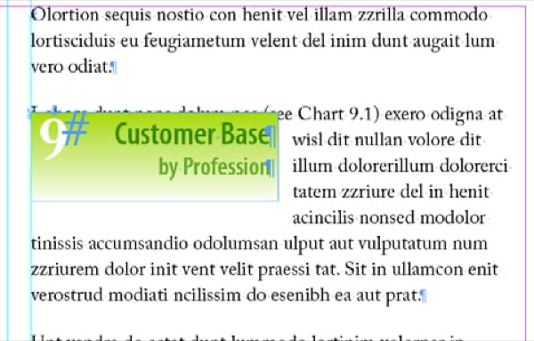
The Anchored Position section (in the middle of the dialog box) controls object position relative to the text to which it’s tethered. In Figure 7, for example, on the left-read page in this spread, the top-right corner of the anchored object is set to align to the outside edge of the text frame and vertically aligns with the anchor marker—the location where the object was pasted into the text (just after “see Chart 9.1”).

Figure 7. These options cause the object to align to the outside edge of the text frame.
If the line of text reflows onto a right-read page, the opposite will happen, because Relative to Spine is checked: The top-left corner of the object will align to the outside, or right, edge of the frame.
Let’s say you change the Anchored Position: Reference Point to inside. This would shove the anchored object toward the spine (inside the text frame in this case), aligning its top-right corner with the edge of the text frame closer to the spine (Figure 8).

Figure 8. Setting the anchored position relative to the inside of the text frame sends the anchored object toward the spine yet keeps it within the text frame.
Beneath the Reference Point grid, in the Anchored Position section, you have granular control over the length and angle of your anchored object’s invisible tether line. You can specify the horizontal or x-axis placement as being relative to the following:
- Anchor Marker: The anchor marker is at the actual point of insertion (where you pasted your anchored object). If that happens to be in the middle of a line of text, all object positioning will be relative to the center of the text line.
- Column Edge: In multiple-column layouts, this option will keep the object’s positioning relative to the edge of the column in which the marker appears, wherever that may hoist on the page.
- Text Frame: Positioning is relative to the bounding box of the text frame, regardless of the number of columns it may contain and of which column actually contains the marker.
- Page Margin: The object will be absolutely positioned horizontally relative to the margin, either inside or outside, regardless of the location or size of the text frame containing its anchor marker.
- Page Edge: Like Page Margin, this option allows absolute horizontal positioning relative to the inside or outside edge of the page (Figure 9).

The Y Relative To popup menu has similar options that let you control the vertical positioning of the anchored object, with additional options to align the object to the baseline, cap height, or top of leading of the text line on which the anchor marker resides. Both X and Y have offset measurement fields for precise positioning through positive or negative values.
Turning on the Keep within Top/Bottom Column Boundaries checkbox—which is available only when Y Relative To is set to one of the text line options—prevents the anchored object from extending above or below the area of the text column even if the options above would have pushed it beyond. To set my graph into the outside margin of the page (Figure 10), I used the following settings:
- Relative to Spine: checked
- Anchored Object: Reference Point set to inside-top corner
- Anchored Position: Reference Point set to outside
- X Relative to: text frame with a 0.2-inch offset (matching the 0.2-inch column gutter)
- Y Relative to: Line (Cap Height) with no offset
- Keep within Top/Bottom Column Boundaries: checked

Figure 10. My first chart, in position relative to its anchor marker (next to the words “see Chart 9.1”)
5. Building up the flotilla
If your document will require multiple objects to be anchored with the same settings as the first, reselect the first anchored object with the Selection tool and make a new object style from it. Anchor options are among the attributes stored and applied by object styles.
Once you’ve created or placed your additional anchored candidates, cut and paste them into the text as usual. Then, instead of going through the whole Anchored Object Options process again, simply click on the object style you created.
Of course, if the only attributes they have in common are their anchoring options, edit your object style ahead of time and turn off all but the Anchored Object Options (Figure 11).

Figure 11. Object styles record and apply Anchored Object Options.
6. Navigating by the stars
Got your sea legs under you? Good. Let’s take her out. An alternative to creating your content and then turning it into an anchored object is building containers as anchored objects and then filling them up later.
The two methods are very similar. In this technique, begin with a predefined object style—your own or InDesign’s default Basic Graphic Frame or Basic Text Frame.
With the Type tool, click within your main text flow at the location desired for the anchor marker. Choose Object > Anchored Object > Insert to bring up the familiar Insert Anchored Object dialog box (Figure 12). The Object Options section at the top is the new part here—that, and the absence of a live preview.

Figure 12. The Insert Anchored Object dialog box.
In the Content popup menu, select the container’s type of content: Text, Graphics, or Unassigned; like InDesign’s hand-drawn frames, the content type you choose here can be changed easily at any time afterward.
Next, choose the object style to act as a template for your new anchored object; like any other object, this, too, can be changed after the fact. If Content is set to Text, the Paragraph Style drop-down will light up, allowing you to select a single paragraph style to apply to the contents of your anchored object.
Finally, determine the height and width of the anchored object itself. The rest of the options you already know. After you click on OK, InDesign will create the anchored object as specified.
To adjust the object’s positioning, return to Object >Anchored Object > Options. At first, recognizing differences in terminology, such as Anchored Object: Reference Point and Anchored Position: Reference Point can be like stepping aboard a schooner and trying to discern a lugsail from a skysail. And, like sails, the effect of each setting is relative to all the other settings.
But after you get used to the terminology and the sometimes confusing icons, anchored objects aren’t really very difficult. But, most of all, remember: Anchored objects are a misnomer. InDesign raises the anchors of illustrations, pull quotes, charts, and other objects that support text. Now they sail, as they should, amidst, ahead of, behind, or alongside their lead ship, freed from the moorings of pages.
The anchor heaves, the ship swings free,
The sails swell full. To swea, to sea!
—Thomas Lovell Beddoes
This article was last modified on December 18, 2024
This article was first published on October 1, 2005
Commenting is easier and faster when you're logged in!

Recommended for you

Create Text Highlighting with a Custom Edge
Use this simple trick to create customizable highlighting to fit any piece of te...

Diagonal Headings in InDesign Tables
Making headings in a table appear diagonally isn't that hard, but you have to us...

Creating Auto-Size Speech Bubbles
A while back, I answered a question on the InDesign User Forum about how to make...