

Using InDesign as a CAD Tool

by Olav Martin Kvern
I like to build things. Physical things, not just software and page layouts. In fact, I like to build synthesizers and robotic musical instruments. Yes, I am a weirdo. Don’t run away just yet—even though you may not be doing this yourself, there’s a reasonabyly good chance that you’ll be able to use some of the tools that I’ve created in your everyday InDesign work.
To build physical things, you need parts. Computer Aided Design (CAD) tools exist to help you turn your design ideas into drawings, which can, in turn, be used to control machines, such as 3D printers or CNC machines. (“CNC” stands for “Computer Numeric Control,” and CNC machines are usually digitally controlled routers or lathes.)
And to design the parts for my musical instruments, I needed a CAD program.
Looks Just Like a Nail
The trouble is that the user interfaces of CAD programs have nowhere near the sophistication of InDesign. Even the relatively modern SketchUp or Autodesk 123D seem a bit clunky when you’re accustomed to InDesign’s drawing tools. Sure, the 3D CAD tools can do a lot more, but all I need is a way to define a path that’s cut through a flat sheet of acrylic.
There’s an old saying that goes, “If the only tool you have is a hammer, everything starts to look like a nail.” My hammer is InDesign. I realized that I could write scripts that would convert InDesign paths and path points into cutting instructions (“toolpaths”) for a CNC machine. CNC machines are driven by G-code, a programming language composed of simple operations (move, set speed, etc.) and geometric coordinates. An example line of G-code looks like this.
g0 x 100 y 100;
“g0” means, “move at the fastest speed you can manage,” while “x 100 y 100” specifies a point 100 units (mm, in my case) from a defined zero point. It’s just like moving an object using InDesign’s Control panel or Transform panel.
A CNC machine can also (at a minimum) control the vertical axis, or “z,” so our G-code is more likely to look something like this:
g0 z 30;
g0 x 0 y 0;
g0 z 0;
g0 x 100 y 100;
g0 z 30;
If you’re following along, you can see that we’ve moved the z axis (and, therefore, the router bit that does the cutting) up, then we move to the x, y zero point, lower the router to zero (probably drilling through whatever it is that we’re cutting), move the router to x 100, y 100, and then raise the router. At this point, we’ve cut a diagonal line from x 0, y 0 to x 100, y 100. With any luck, we haven’t punched the router bit through part of the CNC machine (as happened in my first experiment), and we haven’t broken the router bit (which can happen if the material we’re cutting is too thick to cut in a single pass).
Get the idea? With InDesign scripting, I can get the geometric coordinates of the path points on a path, and I can convert them to G-code that I can then use to drive my (small, semi-homebrew) CNC machine. I can make parts from wood, plastic, or metal.
(In case you’re wondering: For actually sending the G-code to my CNC machine, I use Mach 3—which looks like a Visual Basic project run wildly amok, but it does the job.)
Further Explorations
CAD programs and InDesign share a variety of tools that come in handy when you’re trying to define an object by its geometry—specifically pathfinder operations, such as Add, Subtract, Intersect, and so on (see the options under the Object>Pathfinder submenu). G-code doesn’t really know about Bezier curves, so we need to convert curves into a series of short straight line segments—and we can do that using the AddPoints.jsx script that comes with InDesign.
Then I created a script that modifies InDesign’s menus, putting the most-used menu options for working with paths on the context menu. I’ve shared that script already in a previous blog post.

Path operations added to the Layout context menu.
But there’s more that we need to do to convert InDesign paths to toolpaths. For one thing, a router bit has a specific diameter. If you simply move the router bit along the path you’ve drawn in InDesign, it’ll cut inside the area by half of the diameter of the router bit. To avoid this, you’ll need to offset the path by that distance. Why not just add that value as you scale/resize the path? That will only work when the path is symmetrical around its center point—a circle or a rectangle. For more complex paths, you have to turn elsewhere.
In Illustrator, you’ve got access to the path operation “Offset Path,” which creates a new version of a path that’s offset by a given distance from the original path. I’ll always avoid Illustrator if I can, but I didn’t feel like doing the math required to implement the feature in InDesign (it’s not trivial). However, I did know that there is an InDesign feature that I could use (abuse?) to accomplish the same task: text wrap—a feature I ordinarily despise. [Editor’s note: Text wrap has been a source of debate between Olav and David Blatner for almost 20 years. We’ll ask them to discuss the pros and cons in another article sometime.]
When you apply a Contour-type text wrap to an object, you’re creating a path around that object—and you can specify an offset distance. The text wrap path is accessible via scripting. That means that we could apply a text wrap with a given offset, then capture the path and path points of that path, turn off text wrap, and then create the a new path from those geometric coordinates. I wrote the script OffsetPath.jsx to do just this.
You can download this and the other scripts in this article at siliconpublishing.com. [NOTE: They removed the script. However, thanks to a reader who found it on the wayback machine, we have posted it here.]

Select a path and run the OffsetPath.jsx script. The script will present a dialog box where you can enter the offset value you want. Note that you can enter measurement values using standard InDesign measurement overrides. The basic unit for the InDesign Dialog object is points, but I can enter the value I want in millimeters.
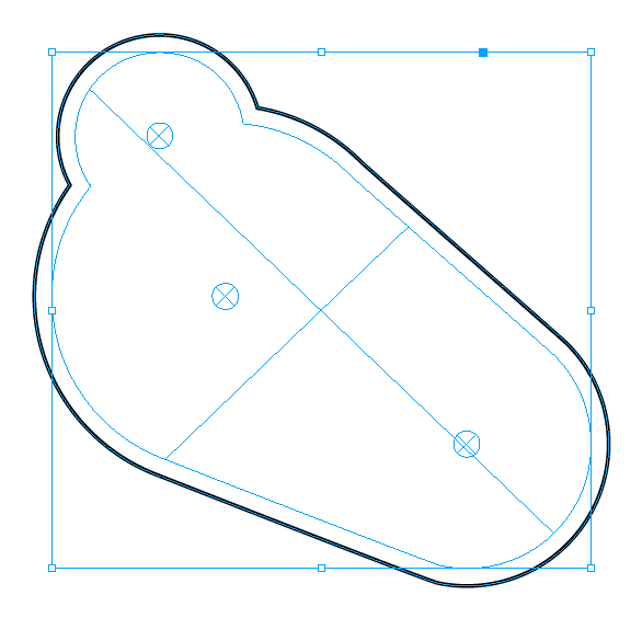
Click the OK button, and InDesign creates a new path, offset from the selected path by the distance you specified.
The only trouble with this approach is that the paths generated using the Text Wrap feature will sometimes have rounded corners at corners of a path. As it happens, that’s exactly what I want, or close enough. I have started work on a script I’m calling FixCorners.jsx, a “clean-up” script that adjusts corners that fall within a given radius (the diameter of the router bit)—but it is not yet ready for prime time. So in the meantime, we need to fix some corners manually when necessary.
Connecting Centers
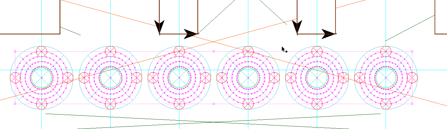
Another, admittedly low-tech, way to create a toolpath is this: create a circle that is the diameter of the router bit you intend to use, then position copies of that circle around the original path. When you connect the centers of all of the circles, in order, you’ll have a toolpath that is offset from the original path by half of the diameter of the circle.
Since connecting the centers of the circles is a bit boring, I created another script, ConnectCenters.jsx, that automates the process—like a big game of “dot-to-dot.”
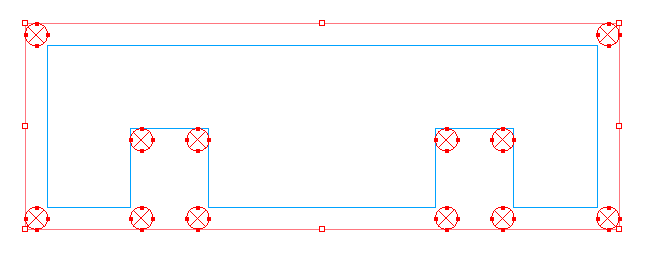
Select objects in the order in which you want to draw the new path…

…then double-click the ConnectCenters.jsx script. InDesign will draw a closed path through the center of each of the objects you selected.
Converting InDesign Paths to G-Code
Now that we’ve got the InDesign paths set up, we need to convert them to toolpaths: G-code to drive the CNC machine. I do that with a script named “IterativePathCuts.jsx”—“Iterative,” because the G-code will move the router bit over a given path a specified number of times, going slightly deeper with each pass.
You can control the vertical movement of the z axis (and, therefore, the router bit) using the Step field in the dialog box. For softer materials (plastic, wood) and larger-diameter router bits (.25 inch/6.35 mm, or for example), you can probably get away with a single pass; for harder materials (aluminum, brass), or smaller-diameter router bits (I typically use .0625 inch/1.588 mm bits), you’ll probably want to use more passes and smaller vertical steps. Using more steps can also produce a smoother edge on your cut pieces. The Interim Z field controls the vertical axis position between cuts—it’s a good idea to lift the router bit well above the surface of the piece you’re cutting before moving to a new starting point. I know, because I’ve forgotten about this step many times. At best, the result is loud cursing and screaming; at worst, it’s a broken router bit and a ruined part. Did I mention that carbide router bits are expensive? Or that a single part can sometimes take hours to cut?
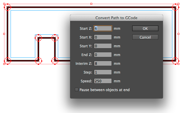
Select a path or set of paths and run the IterativePathCuts.jsx script. The script will present a dialog box where you can control the vertical axis of the CNC machine it moves the router. The Step field controls the vertical distance between each cut. When you click the OK button, the script will ask you where you want to store the G-code file. Make certain that you enter the file extension “.nc” at the end of the G-code file name.
Note that you do not need to cut all of the way through the material—you can stop the router bit at any vertical coordinate. That’s what the End Z field is for—setting the point at which you’ll stop cutting.
Saving and Restoring Selections
I set up the IterativePathCuts.jsx script to follow the selection order of objects. By selecting objects in a particular order, I can control the distances that the router bit needs to travel as it goes from one part to another. This can reduce the time it takes to cut a given piece tremendously. CAD drawings, however, can be quite complex. After about the tenth time I’d forced myself to select the same sixty paths in a specific order, I realized that I needed to automate the process.
The result was SaveSelection.jsx, which saves a selection in a document, and RestoreSelection.jsx, which selects the same objects again, in the same order. It’s very simple to use—select a set of objects (in order, if necessary), then double-click SaveSelection.jsx). The script will display a dialog box where you can name the selection (or choose an existing selection to replace). If you’re creating a new saved selection, enter a name and click the OK button. If you’re replacing an existing saved selection, select its name from the dropdown menu (and do not enter any text in the New Selection field), then click the OK button. Either way, the selection will be saved in the document.

If the document does not contain any saved selections, the dialog presents a single field. Enter a name for the selection and click the OK button.

If the document contains saved selections, the dialog box will give you the option to either create a new saved selection (enter a name for the selection in the New Selection field) or to save over an existing selection (select the name of the saved selection from the Saved Selection dropdown menu).
When the time comes to make that selection again, double-click the RestoreSelection.jsx script. The script will display a dialog box that lists the selections stored in the document. Select one of the saved selections from the dropdown menu and click the OK button. InDesign will then attempt to select the objects. If the original objects still exist in the document (i.e., they haven’t been deleted, cut, or pasted), InDesign will select the objects and display the selection. If the script can find some of the objects, it will select those that it can find. If the script can’t any of the objects, it will display a dialog box apologizing for its failure. If the script can’t select the objects for some reason (they’ve moved to different pages, to a locked layer, or are locked against selection), you’ll see a different apology.

To restore a saved selection, double-click the RestoreSelection.jsx script in the Scripts panel. InDesign will display the Restore Selection dialog box. Select the saved selection you want to restore from the Saved Selection dropdown menu, then click the OK button.
If it’s possible to restore the selection, InDesign will select the objects.
Currently, SaveSelection.jsx and RestoreSelection.jsx support page items—rectangles, ellipses, polygons, graphic lines, and text frames. At some point, I’ll probably add support for text selections.
Limited Only by Your Patience
I use these software tools to help make robotic musical instruments (such as the guitar-picking machine).You might use them for something completely different—sign making comes immediately to mind. Wouldn’t it be cool to create carved signs, in wood, using InDesign’s fantastic typesetting abilities? With the scripts I’ve presented here, you could do that (after converting the text to paths, of course).
Note, at the same time, that these tools are very rough. I haven’t bothered to put the kind of effort into them that would make them “foolproof” for anyone other than the specific fool at hand (i.e., me). That said, the ability to save/restore selections, for example, seems like it could help with complex layouts (are there any mapmakers in the house?). OffsetPath.jsx could really help the next time you’re creating logos based on paths made from converted text characters.
I think that some of these scripts are useful—even if you’re not building musical robots.
[Olav Martin Kvern is Senior Solutions Architect at Silicon Publishing Inc., and the co-author of Real World InDesign]
I really enjoyed this presentation at PePcon! And so very cool to see someone else that has used InDesign to output files for a CNC machine. Here is one I did a few years ago that used a flatbed printer and CNC machine to create plastic postcards:Variable Data Meets Large Format Printing.
I enjoyed seeing this project written up. I have already talked about it to my brother-in-law, a machinist, who creates miniature engines in his spare time, now I can show him the process.
Next project? Using InDesign to plot course co-ordinates for the [Tardis](https://en.wikipedia.org/wiki/TARDIS)?
And now there are three. Interesting article, but not something I have need of at this time, though the offset path script is promising.
So when do we get to hear Ole and David debate text wrap pro and cons? :)
Ah! Here you go: https://creativepro.com/text-wrap-awesome-evil.php
Hi!
Thanks for all of your tips. I’m looking for the offsetpath script mentioned here, but it doesn’t appear among those at that link… It’s dead? Is there any other way to offset a path in indesign without doing it by hand?
Thanks again!
livio: ah, it appears they moved the page. I updated the link in the article. Here it is: https://www.siliconpublishing.com/about/about_resources.html
Oh, I love you David. You’re like the Red Cross.
Thank you.
Couldn’t find the script either. David, could you please point where to look at.
Hello! I can’t find anywhere most of the script mentioned in this article, can you please add a .zip file to download to this very useful article? I specifically need the OffsetPath.jsx one..
Thanks in advance!
P
Here you go. You have o click through a couple of blog posts to find it.: https://siliconpublishing.com/resources/olescripts/AddPathOperationsToLayoutMenu.jsx.zip
Hello Kelly, and thank you! but I already downloaded this script file.
I need just the OffsetPath.jsx but I can’t find it anywhere in the https://siliconpublishing.com/ website :(
Hello,
Thanks for this great article. I am also looking for OffsetPath.jsx script but cannot find at given link nor elsewhere at website. Can anybody help please. Many thanks in advance.
Add my voice to the chorus that the offsetpath.jsx script is no longer part of the resources page on the Silicon Publishing site. Further searching has turned up nothing. Would love to get a copy of the script. Heck, I’d even pay money for it.
I looking for this script too! :)
Please, give us this great tool!
Thank you!
better to forgot about it, or at least one of the owner of the plugin should write in this page that they don’t want to release it anymore… it would be much more clear and honest.. :(
Found it on the web archive: https://web.archive.org/web/20160422193044/https://www.siliconpublishing.com/resources/olescripts/CADscripts.zip
WOW! that’s great Roman!! Thank you very much!
P
Thanks, Roman. Much appreciated.
Many thanks
EXCELLENT! I have updated the link above in the article so people can download it easily.)
Yay!
Any luck with the FixCorners.jsx script? I need straight corners instead of the rounded ones.